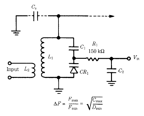
Figure 1 Varactor diode-tuned circuit.
The principal LC tank circuit consists of the main inductor (L1) and a capacitance made up from the series equivalent of C1 and varactor CR1. In addition, you must also take into account the stray capacitance (Cs) that exists in all electronic circuits. The blocking capacitor and series-resistor functions were covered in the preceding paragraphs. Capacitor C2 is used to filter the tuning voltage, Vin.
Because the resonant frequency of an LC-tuned tank circuit is a function of the square root of the inductance-capacitance product, we find that the maximum/minimum frequency of the varactor-tuned tank circuit varies as the square root of the capacitance ratio of the varactor diode. This value is the ratio of the capacitance at minimum reverse bias over capacitance at maximum reverse bias. A consequence of this is that the tuning characteristic curve (voltage vs frequency) is basically a parabolic function.