The main tuning capacitors in old radios are often full of crud, grease, and dust. Similarly, ham radio operators working the hamfest circuit looking for linear amplifier and antenna tuner parts often find just what they need, but the thing is all gooped-up. Several things can be done about it. First, try using dry compressed air. It will remove dust, but not grease. Aerosol cans of compressed air can be bought from a lot of sources, including automobile parts stores and photography stores.
Another method, if you have the hardware, is to ultrasonically clean the capacitor. The ultrasonic cleaner, however, is expensive; unless you have one, do not rush out to lay down the bucks.
Still another way is to use a product, such as Birchwood Casey Gun Scrubber. This product is used to clean firearms and is available in most gun shops. Firearms goop-up because gun grease, oil, unburned powder, and burned powder residue combine to create a crusty mess that is every bit as hard to remove as capacitor gunk. A related product is the degunking compound used by auto mechanics.
At one time, carbon tetrachloride was used for this purpose . . . and you will see it listed in old radio books. However, carbon tet is now well-recognized as a health hazard. DO NOT USE CARBON TETRACHLORIDE for cleaning, despite the advice to the contrary found in old radio books.
วันพฤหัสบดีที่ 24 มิถุนายน พ.ศ. 2553
วันพุธที่ 5 พฤษภาคม พ.ศ. 2553
Varactor applications
Varactors are electronically variable capacitors. In other words, they exhibit a variable capacitance that is a function of a reverse bias potential. This phenomenon leads to several common applications in which capacitance is a consideration. Figure 1 shows a typical varactor-tuned LC tank circuit. The link-coupled inductor (L2) is used to input RF to the tank when the circuit is used for RF amplifiers (etc.).

Figure 1 Varactor diode-tuned circuit.
The principal LC tank circuit consists of the main inductor (L1) and a capacitance made up from the series equivalent of C1 and varactor CR1. In addition, you must also take into account the stray capacitance (Cs) that exists in all electronic circuits. The blocking capacitor and series-resistor functions were covered in the preceding paragraphs. Capacitor C2 is used to filter the tuning voltage, Vin.
Because the resonant frequency of an LC-tuned tank circuit is a function of the square root of the inductance-capacitance product, we find that the maximum/minimum frequency of the varactor-tuned tank circuit varies as the square root of the capacitance ratio of the varactor diode. This value is the ratio of the capacitance at minimum reverse bias over capacitance at maximum reverse bias. A consequence of this is that the tuning characteristic curve (voltage vs frequency) is basically a parabolic function.
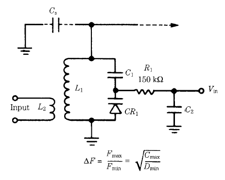
Special variable capacitors ตัวเก็บประจุปรับค่าได้แบบพิเศษ
In the preceding sections, the standard forms of variable capacitor were covered. These capacitors are largely used for tuning radio receivers, oscillators, signal generators, and other variable frequency LC oscillators. This section covers some special forms of variable capacitor.
Split-stator capacitors
The split-stator capacitor is one in which two variable capacitors are mounted on the same shaft. The split-stator capacitor normally uses a pair of identical capacitors, each the same value, turned by the same shaft. The rotor is common to both capacitors. Thus, the capacitor will tune either two tuned circuits at the same time or both halves of a balanced-tuned circuit (i.e., one in which the inductor is centertapped and grounded).

Differential capacitors
Although some differential capacitors are often mistaken for split-stator capacitors, they are actually quite different. The split-stator capacitor is tuned in tandem, i.e., both capacitor sections have the same value at any given shaft setting. The differential capacitor, on the other hand, is arranged so that one capacitor section increases in capacitance and the other section decreases in exactly the same proportion. Differential capacitors are used in impedance bridges, RF resistance bridges, and other such instruments. If you buy or build a high-quality RF impedance bridge for antenna measurements, for example, it is likely that it will have a differential capacitor
as the main adjustment control. The two capacitors are used in two arms of a Wheatstone bridge circuit. Be careful of planning to build such a bridge, however. I recently bought the differential capacitor for such an instrument, and it cost nearly $50!
“Transmitting” variable capacitors
The one requirement of transmitting variable capacitors (and certain antenna tuning capacitors) is the ability to withstand high voltages. The high-power ham radio or AM broadcast transmitter will have a dc potential of 1500 to 7500 V on the RF amplifier anode, depending on the type of tube used. If amplitude-modulated,the potential can double. Also, if certain antenna defects arise, then the RF voltages in the circuit can rise quite high. As a result, the variable capacitor used in the final amplifier anode circuit must be able to withstand these potentials.
Two forms of transmitting variables are typically used in RF power amplifiers and antenna tuners. Figure 7 shows a transmitting air variable capacitor. The shaft of this particular capacitor is nylon, so it can be mounted either with the frame grounded or with the frame floating at high voltage. The other form of transmitting variable is the vacuum variable. This type of capacitor is a variation of the piston capacitor, but it has a vacuum dielectric (K factor = 1.0000). The model shown in Fig. 8 is a 18- to 1000-pF model that is driven from a 12-Vdc electric motor. Other vacuum variables are manually driven.

Figure 7 a transmitting air variable capacitor

Figure 8 Vacuum variable capacitor
Solid-state capacitors
One of the problems with variable capacitors is that they are large, bulky things (look at all the photos) that must be mechanically operated. Modern electronic circuits, including most radios today, are electrically tuned using a varicap diode for the (Ct) of a PN junction diode is a function of the reverse bias voltage applied across the diode. The varicap (a.k.a. “varactor”) is therefore a variable capacitor in which the capacitor is a function of an applied voltage. Maximum capacitances run from 15 to 500 pF, depending on the type. capacitor function. These “capacitors” operate because the junction capacitance
Varactors come in several different standard diode packages, including the twoterminal “similar to 182” package shown in Fig. 9. Some variants bevel the edge of the package to denote which is the cathode. In other cases, the package style will be like other forms of diode. Varactors are used in almost every form of diode package, up to and including the package used for 50- to 100-A stud-mounted rectifier diodes.

Fig. 9 Typical varactor cases.
Variable capacitors in RF circuits

Like all capacitors, variable capacitors are made by placing two sets of metal plates parallel to each other (Fig. A) separated by a dielectric of air, mica, ceramic, or a vacuum. The difference between variable and fixed capacitors is that, in variable capacitors, the plates are constructed in such a way that the capacitance can be changed. There are two principal ways to vary the capacitance: either the spacing between the plates is varied or the cross-sectional area of the plates that face each other is varied.

(A) Schematic view
Figure B shows the construction of a typical variable capacitor used for the main tuning control in radio receivers. The capacitor consists of two sets of parallel plates. The stator plates are fixed in their position and are attached to the frame of the capacitor. The rotor plates are attached to the shaft that is used to adjust the capacitance.

(B) construction
Another form of variable capacitor used in radio receivers is the compression capacitor shown in Fig. C. It consists of metal plates separated by sheets of mica dielectric. In order to increase the capacitance, the manufacturer may increase the area of the plates and mica or the number of layers (alternating mica/metal) in the assembly. The entire capacitor will be mounted on a ceramic or other form of holder. If mounting screws or holes are provided then they will be part of the holder assembly.

(C) mica compression variable capacitor
Still another form of variable capacitor is the piston capacitor shown in Fig. D. This type of capacitor consists of an inner cylinder of metal coaxial to, and inside of, an outer cylinder of metal. An air, vacuum, or (as shown) ceramic dielectric separates the two cylinders. The capacitance is increased by inserting the inner cylinder further into the outer cylinder.

(D) piston variable capacitor.
The small-compression or piston-style variable capacitors are sometimes combined with air variable capacitors. Although not exactly correct word usage, the smaller capacitor used in conjunction with the larger air variable is called a trimmer capacitor. These capacitors are often mounted directly on the air variable frame or very close by in the circuit. In many cases, the “trimmer” is actually part of the air variable capacitor.

Trimmer capacitor
There are actually two uses for small variable capacitors in conjunction with the main tuning capacitor in radios. First, there is the true “trimmer,” i.e., a small-valued variable capacitor in parallel with the main capacitor (Fig. 2A). These trimmer capacitors (C2) are used to trim the exact value of the main capacitor (C1). The other form of small capacitor is the padder capacitor (Fig. 2B), which is connected in series with the main capacitor. This error in terminology is calling both series and parallel capacitors “trimmers,” when only the parallel connected capacitor is properly so-called.

(2A) Trimmer capacitor connected in parallel with the main tuning capacitor

(2B) padder capacitor is connected in series with the main tuning capacitor.
The capacitance of an air variable capacitor at any given setting is a function of how much of the rotor plate set is shaded by the stator plates. In Fig. 3A, the rotor plates are completely outside of the stator plate area. Because the shading is zero, the capacitance is minimum. In Fig. 3B, however, the rotor plate set has been slightly meshed with the stator plate, so some of its area is shaded by the stator. The capacitance in this position is at an intermediate-value. Finally, in Fig. 3C, the rotor is completely meshed with the stator so the cross-sectional area of the rotor that is shaded by the stator is maximum. Therefore, the capacitance is also maximum. Remember these two rules:

(3A) capacitance is minimum

(3B) intermediate capacitance

(3C) maximum capacitance.

1. Minimum capacitance is found when the rotor plates are completely unmeshed with the stator plates; and
2. Maximum capacitance is found when the rotor plates are completely meshed with the stator plates.

Figure 4 single-section variable capacitor
Figure 4 shows a typical single-section variable capacitor. The stator plates are attached to the frame of the capacitor, which in most radio circuits is grounded. Front and rear mounts have bearing surfaces to ease the rotor’s action. The ganged variable capacitor

(Fig. 5) Dual section air variable capacitor.
(Fig. 5) was invented to provide tracking between two related LC-tuned circuits, as in a radio receiver. Such capacitors are basically two (in the case of Fig. 5) or more variable capacitors mechanically ganged on the same rotor shaft.
In Fig. 5, both sections of the variable capacitor have the same capacitance, so they are identical to each other. If this capacitor is used in a superheterodyne radio, the section used for the local oscillator (LO) tuning must be padded with a series capacitance in order to reduce the overall capacitance. This trick is done to permit the higher-frequency LO to track with the RF amplifiers on the dial.
In many superheterodyne radios, you will find variable tuning capacitors in which one section (usually the front section) has fewer plates than the other section. One section tunes the RF amplifier of the radio, and the other tunes the local oscillator. These capacitors are sometimes called cut-plate capacitors because the LO section plates are cut to permit tracking of the LO with the RF.
สมัครสมาชิก:
บทความ (Atom)